Suzuki GSX-R 1000 Service Manual: Self-diagnostic procedures
Use of mode select switch
Note
|
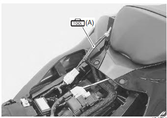
- Remove the front seat. Refer to “exterior parts removal and installation” in section 9d (page 9d- 6).
- Connect the special tool to the mode select switch coupler.
Special tool
 (a): 09930–82720 (mode selection
switch)
- Start the engine or crank the engine for more than 4 seconds.
- Turn the special tool’s switch on.
- Check the dtc to determine the malfunction part.
Refer to “dtc table” .
Special tool
(a): 09930–82720 (mode selection
switch)
- After repairing the trouble, turn off the ignition switch and turn on again. If dtc is indicated (c00), the malfunction is cleared.
Note
|
- Turn the ignition switch off and disconnect the special tool from the mode select switch coupler.
- Reinstall the front seat.
Use of sds
Note
|
- Remove the front seat. Refer to “exterior parts removal and installation” in section 9d (page 9d- 6).
- Set up the sds tools. (Refer to the sds operation manual for further details.)
Special tool
 (a): 09904–41010 (suzuki diagnostic
system set)
 (b): 99565–01010–020 (cd-rom
ver.20)
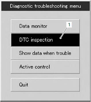
- Click the dtc inspection button (1).
- Start the engine or crank the engine for more than 4 seconds.
- Check the dtc to determine the malfunction part.
Refer to “dtc table” .
Note
|
- After repairing the trouble, clear to delete history code (past dtc). Refer to “use of sds diagnosis reset procedures” .
- Close the sds tool and turn the ignition switch off.
- Disconnect the sds tool and install the front seat.

 Use of sds diagnosis reset procedures
Note
the malfunction code is memorized in the
ecm also when the lead wire coupler of any
sensor is disconnected. Therefore, when a
lead wire coupler has been disconnected at
the ...
Other materials:
Turn signal / side-stand relay removal and
installation
Removal
Turn the ignition switch off.
Remove the frame cover assembly. Refer to “exterior parts removal and
installation” in section 9d .
Remove the turn signal/side-stand relay (1).
Installation
Install the turn signal/side-stand relay in the reverse
order of removal ...
Rear brake pedal adjustment
The rear brake pedal position
must be properly adjusted at all
times or the disk brake pads will
bear against the disk causing
damage to the pads and to the
disk surface. Adjust the brake
pedal posit~ on in the following
manner:
Loosen lock nut 1, and turn
the push rod 2 to locate t ...
Evaporative emission control system
diagram (only for e-33)
Fuel tank
Fuel-vapor separator
Fuel pump
Fuel feed hose
Fuel shut-off valve
Iap sensor
Surge hose
Evap canister
Purge hose
Evap system purge control solenoid valve
Fue
Hc vapor
Fresh air
Vacuum
...