Suzuki GSX-R 1000 Service Manual: DTC “c29” (p1654-h/l): secondary throttle position sensor (stps) circuit malfunction
Detected condition and possible cause
|
Detected condition |
Possible cause |
||
| C29 | Output voltage is not within the following
range. Difference between actual throttle opening and opening calculated by ecm is larger than specified value. 0.15 V ≤ Sensor voltage < 4.85 V |
|
|
| P1654 | H | Sensor voltage is higher than specified value. | |
| L | Sensor voltage is lower than specified value. | ||
Wiring diagram

Troubleshooting
| Caution when using the multi-circuit tester, do not strongly touch the terminal of the ecm coupler with a needle pointed tester probe to prevent terminal damage. |
| Note after repairing the trouble, clear the dtc using sds tool. Refer to “use of sds diagnosis reset procedures” . |
C29 (use of mode select switch)
|
Step |
Action |
Yes |
No |
|
1 |
Special tool Tester knob indication
voltage ( Stp sensor input voltage 4.5 – 5.5 V ((+) terminal: r – (–) terminal: ground, (+) terminal: r – (–) terminal: b/br)
Is the voltage ok? |
Go to step 3. |
|

 (a): 09900–25008 (multi
 )
)
P1654-h (use of sds)
|
Step |
Action |
Yes |
No |
|
1 |
Special tool Tester knob indication
continuity (
Special tool
(a):
(b):
Tester knob indication
continuity test ( Ecm couplers (harness side)
Is the continuity ok? |
Go to step 3. | Y/w wire shorted to vcc, or b/br wire open. |
 (a): 09900–25008 (multi
 )
)

P1654-l (use of sds)
|
Step |
Action |
Yes |
No |
|
1 |
Special tool Tester knob indication
continuity test (
Special tool Tester knob indication
continuity test ( Ecm couplers (harness side)
Is the continuity ok? |
Go to step 2. | R or y/w wire open, or y/w wire shorted to ground. |
|
2 |
Special tool
Tester knob indication
voltage ( Stp sensor input voltage 4.5 – 5.5 V ((+) terminal: r – (–) terminal: ground, (+) terminal: r – (–) terminal: b/br)
Is the voltage ok? |
Go to step 3. | Open or short circuit in the r or b/br wire. |
|
3 |
Special tool Tester knob indication
voltage ( Stp sensor output voltage secondary throttle valve is closed: approx. 0.7 V secondary throttle valve is opened: approx. 4.1 V ((+) terminal: y/w – (–) terminal: b/br)
Is the voltage ok? |
|
If check result is not satisfactory, replace the stp sensor with a new one. Refer to “stp sensor removal and installation” in section 1c . |


 )
)


 DTC “c28” (p1655): secondary throttle
valve actuator (stva) malfunction
DTC “c28” (p1655): secondary throttle
valve actuator (stva) malfunction
Detected condition and possible cause
Detected condition
Possible cause
The operation voltage does not reach the stva.
Ecm does not receive communication signal from the ...
 DTC “c31” (p0705): gp switch circuit
malfunction
DTC “c31” (p0705): gp switch circuit
malfunction
Detected condition and possible cause
Detected condition
Possible cause
No gear position switch voltage
Gp switch voltage is not within the following range.
Gp switch ...
Other materials:
Balancer shaft journal bearing inspection
and selection
Refer to “engine bottom side disassembly” (page 1d-
49).
Refer to “engine bottom side assembly” .
Inspection
Inspect the bearing surfaces for any signs of fusion,
pitting, burn or flaws. If any, replace them with a
specified set of bearings.
Selection
Place the plastigauge axial ...
Water hose inspection
Inspect the water hoses in the following procedures:
remove the side cowlings. Refer to “exterior parts
removal and installation” in section 9d (page 9d-
6).
Check the water hoses for crack, damage or engine
coolant leakage. If any defect is found, replace the
water hose wi ...
Ecm removal and installation
Removal
Remove the frame covers. Refer to “exterior parts
removal and installation” in section 9d (page 9d-
6).
Disconnect the battery (–) lead wire.
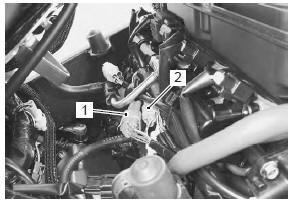
Remove the tool set (1) and prop stay (2).
Disconnect the hose clamp (3) (e-33 only) and
starter relay (4).
Remo ...