Suzuki GSX-R 1000 Service Manual: General description
Combination meter system description
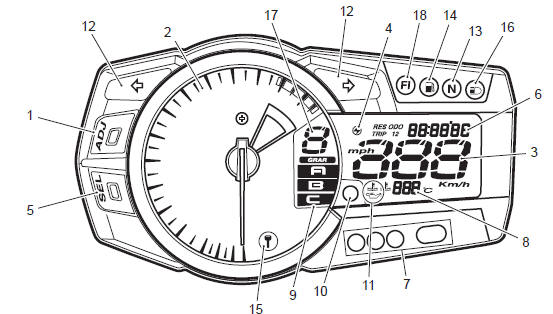
This combination meter mainly consists of a stepping motor, lcd (liquid crystal display) and leds (light emitting diode).
The tachometer pointer is driven by the stepping motor.
The lcds indicate followings: speed, odo / trip 1 / trip 2 / fuel reserve trip / clock / fi (dtc) / lap time counter / panel light brightness, gear position, engine rpm indicator, oil pressure indicator, engine coolant temperature and drive mode position.
Led (light emitting diode)
Led is used for the illumination light and each indicator light.
Led is maintenance free. Led is less power consuming and more resistant to vibration resistance compared to the bulb.
Engine rpm indicator light
This speedometer is equipped the engine revolution indicator light. The engine revolution indicator light is adjustable from 5 000 – 13 750 r/min. (From 5 000 r/min to 10 000 r/min, every 250 r/min and 10 000 r/min to 13 750 r/min, every 50 r/min: initial setting: 11 000 r/min)
|


Other materials:
Voltage check
If voltage is supplied to the circuit being checked, voltage
check can be used as circuit check.
With all connectors/couplers connected and voltage
applied to the circuit being checked, measure
voltage between each terminal and body ground.
If measurements were taken as shown ...
Specifications
Service data
Thermostat + radiator + fan + coolant
Tightening torque specifications
Note
the specified tightening torque is described in the following.
“Water hose routing diagram” “water pump components” “water
pump construction”
Reference: for the tig ...
Air cleaner
The air cleaner element must be
kept clean to provide good engine
power and g1as mileage. If you use
your motorcycle under normal
low-stress conditions, you should
service the air cleaner at the intervals
specified. If you ride in dusty,
wet, or muddy conditions, you will
need to inspect the ...