Suzuki GSX-R 1000 Service Manual: Self-diagnostic procedures
Use of mode select switch
Note
|
- Remove the front seat. Refer to “exterior parts removal and installation” in section 9d (page 9d- 6).
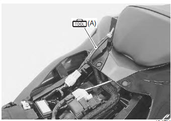
- Connect the special tool to the mode select switch coupler.
Special tool
 (a): 09930–82720 (mode selection
switch)
- Start the engine or crank the engine for more than 4 seconds.
- Turn the special tool’s switch on.
- Check the dtc to determine the malfunction part.
Refer to “dtc table” .
Special tool
(a): 09930–82720 (mode selection
switch)
- After repairing the trouble, turn off the ignition switch and turn on again. If dtc is indicated (c00), the malfunction is cleared.
Note
|
- Turn the ignition switch off and disconnect the special tool from the mode select switch coupler.
- Reinstall the front seat.
Use of sds
Note
|
- Remove the front seat. Refer to “exterior parts removal and installation” in section 9d (page 9d- 6).
- Set up the sds tools. (Refer to the sds operation manual for further details.)
Special tool
 (a): 09904–41010 (suzuki diagnostic
system set)
 (b): 99565–01010–020 (cd-rom
ver.20)
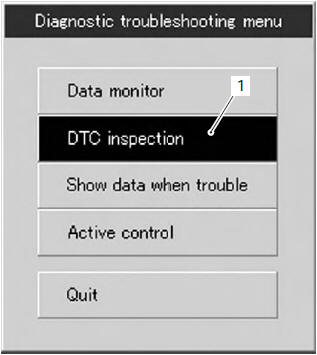
- Click the dtc inspection button (1).
- Start the engine or crank the engine for more than 4 seconds.
- Check the dtc to determine the malfunction part.
Refer to “dtc table” .
Note
|
- After repairing the trouble, clear to delete history code (past dtc). Refer to “use of sds diagnosis reset procedures” .
- Close the sds tool and turn the ignition switch off.
- Disconnect the sds tool and install the front seat.

 Use of sds diagnosis reset procedures
Note
the malfunction code is memorized in the
ecm also when the lead wire coupler of any
sensor is disconnected. Therefore, when a
lead wire coupler has been disconnected at
the ...
Other materials:
Exhaust control system operation
The excs is operated by the signal supplied from the ecm. The open/close
operation of the excv is performed by
the excva which is controlled by the ecm by changing the current direction of
the actuator motor. The position
sensor (incorporated in the excva) detects the excva movement by measuri ...
Stv actuator removal and installation
Refer to “throttle body disassembly and assembly” in section 1d .
Caution
never remove the stva from the throttle
body.
Isc valve inspection
Refer to “dtc “c40” (p0505 / p0506 / p0507): isc valve circuit malfunction”
in section 1a .
Isc valve removal and installation
Refer t ...
Modification
Modification of the motorcycle, or
removal of original equipment
may render the vehicle unsafe or
illegal. Obey all applicable equipment
regulations in your area.
The frame of this motorcycle is
made of an aluminum alloy.
Therefore, never make any modifications
such as drilling or weldin ...