Suzuki GSX-R 1000 Service Manual: Front fork disassembly and assembly
Refer to “front fork removal and installation” (page 2b- 2).
| Note the right and left front forks are installed symmetrically and therefore the disassembly procedure for one side is the same as that for the other side. |
Disassembly
- Turn the spring pre-load adjuster (1) to the softest position.

- Loosen the front fork cap using the special tool and vise.
| Caution do not clamp the outer tube too tight. |
Special tool (a): 09941–53670 (front fork cap socket wrench (45 mm))

- Loosen the rod guide case installed in the inner tube using the special tool.
Special tool
 (b): 09940–84710 (rod guide case
wrench)
 Hold the Hold the
front fork cap when removing the rod guide case, or it will jump out due to the spring pressure. |

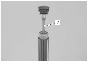
- Remove the piston rod assembly (2).
- Remove the spring collar b (3) and spring (4).

- Drain fork oil and remove the spring collar a (5).

- Remove the dust seal (6).
- Remove the oil seal stopper ring (7).
Caution
|

- Pull out the inner tube from the outer tube.

- Remove the slide bushing (8) from the inner tube.
- Remove the following parts from the inner tube.
- guide bushing (9)
- oil seal spacer (10)
- oil seal (11)
- oil seal stopper ring (7)
- dust seal (6)

- Hold the piston rod assembly with the special tool and vise.
Special tool
 (a): 09941–53670 (front fork cap
socket
wrench (45 mm))
- Loosen the piston rod nut (12) and disassemble the piston rod as shown.


Assembly
Caution
|
- Cover the inner tube with a plastic film.
- Install the following parts to the inner tube.
- new dust seal (1)
- stopper ring (2)
- new oil seal (3)
Caution
|

|
- Remove the plastic film and install the oil seal spacer (4), guide bushing (5) and slide bushing (6) keep them free from dust.
Caution
|

|
- Insert the inner tube into the outer tube.
- Press fit the guide bushing (5) using the special tools.
- Press fit the new oil seal (3) using the special tools until the stopper ring groove on the outer tube can be seen.
Special tool
 (a): 09940–52861 (front fork oil
seal
installer set)

- Install the stopper ring (2).
| Caution make sure that the stopper ring is fitted securely into the groove. |

- Press fit the dust seal (1).

- Insert the spring collar a (7) and spring (8) into the inner tube.

- Insert the spring collar b (9) into the inner tube.
| Caution face the flange “d” of the collar to the spring side. |

|
- Pour specified fork oil until its surface passes the side holes of inner tube.
 : Fork oil 99000–99001–ss5
(suzuki
fork oil ss-05 or equivalent)

- Slowly stroke the outer tube more than ten times to pump out air.
| Note take extreme attention to pump out air completely. |

- Assemble the piston rod and rod guide case (10).
- Tighten the piston rod nut (11) with the special tool and vise.
Tightening torque piston rod nut (a): 28 n·m (2.8 Kgf-m, 20.0 Lbf-ft)

- Insert the piston rod assembly into the inner tube and temporarily tighten the rod guide case by hand.
| Caution insert the piston rod assembly into the inner tube with the outer tube lifted up. Be sure not to damage the piston ring (12) of the rod guide case. |
Special tool
 (b): 09940–84710 (rod guide case
wrench)

- Tighten the rod guide case to the specified torque.
Refer to “rod guide case tightening torque” .
Special tool
 (b): 09940–84710 (rod guide case
wrench)
Tightening torque rod guide case: 90 n·m (9.0 Kgf-m, 65.0 Lbf-ft)

- Pour specified fork oil up to the top of the rod guide case.
 : Fork oil
99000–99001–ss5 (suzuki
fork oil ss-05 or equivalent)

- Push the front fork cap, then stroke the outer tube several times to pump out air.
| Note take extreme attention to pump out the air completely. |

- Hold the front fork vertically and adjust the oil level using the special tool.
Special tool
 (c): 09943–74111 (front fork oil
level
gauge)
Fork oil level “a” 75.0 Mm (2.95 In)

- Apply fork oil to the o-ring (13).
| Caution use new o-ring to prevent oil leakage. |
- Tighten the front fork cap to the specified torque.
| Caution do not clamp the outer tube too tight. |
Tightening torque front fork cap: 35 n·m (3.5 Kgf-m, 25.5 Lbf-ft)
Special tool
 (a): 09941–53670 (front fork cap
socket
wrench (45 mm))

 Front suspension adjustment
After installing the front fork, adjust the spring pre-load
and two kinds of damping force as follows:
Adjust the
left and right front forks to the
same setting.
Spring pre-load ...
 Front fork parts inspection
Refer to “front fork disassembly and assembly” .
Inner and outer tubes
Inspect the inner tube and outer tube for scratches
Slide bushing / guide bushing
Inspect the slide bushing and guide bus ...
Other materials:
Precautions
Precautions for maintenance
The “periodic maintenance schedule chart” lists the recommended intervals for
all the required periodic service work
necessary to keep the motorcycle operating at peak performance and economy.
Maintenance intervals are expressed
in terms of kilometers, miles and mo ...
Engine sprocket removal and installation
Removal
Remove the gearshift link arm (1) from the gearshift
shaft.
Note
mark the gearshift shaft head at which the
gearshift link arm slit set for correct
reinstallation.
Remove the speed sensor (2).
Remove the engine sprocket cover (3).
Support the ...
Turn signal / side-stand relay removal and
installation
Removal
Turn the ignition switch off.
Remove the frame cover assembly. Refer to “exterior parts removal and
installation” in section 9d .
Remove the turn signal/side-stand relay (1).
Installation
Install the turn signal/side-stand relay in the reverse
order of removal ...