Suzuki GSX-R 1000 Service Manual: DTC “c40” (p0505 / p0506 / p0507): isc valve circuit malfunction
Detected condition and possible cause
|
Detected condition |
Possible cause |
|
| C40/P0505 | The circuit voltage of motor drive is unusual. |
|
| C40/P0506 | Idle speed is lower than the desired idle speed. | |
| C40/P0507 | Idle speed is higher than the desired idle speed. | |
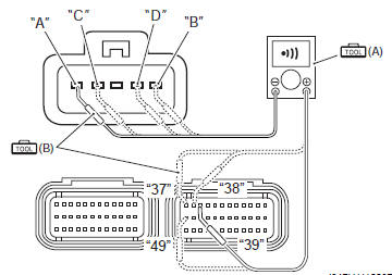
Wiring diagram

Troubleshooting
Caution
|
| Note after repairing the trouble, clear the dtc using sds tool. Refer to “use of sds diagnosis reset procedures” . |
|
Step |
Action |
Yes |
No |
|
1 |
Special tool Tester knob indication
continuity test ( Ecm couplers (harness side)
Is the continuity ok? |
Go to step 2. | Bl, y, g or br wire open |
|
2 |
Special tool
Tester knob indication resistance (Ω) Isc valve continuity ∞Ω¶ (infinity) (terminal . Ground)
Isc valve resistance approx. 80 Ω at 20 °c (68 °f) (terminal: “a” – terminal: “b”, terminal: “c” – terminal: “d”)
Is the resistance ok? |
If wire is ok, intermittent trouble or faulty ecm. | Replace the isc valve with a new one. Refer to “throttle body removal and installation” in section 1d (page 1d- 10). |

 (a): 09900–25008 (multi
 (b): 09900–25009
 )
)


Active control inspection (isc rpm control)
Check 1
- Set up the sds tool. (Refer to the sds operation manual for further details.)
- Check that the engine is running.
- Click the “active control”.
- Click the “isc rpm control” (1).

- Check that the “spec” (2) is idle speed 1 150 ± 100 rpm.
- Check that the “desired idle speed” (3) is within the specified idle rpm.


Check 2
- Click the button (4) and decrease the “spec” (2) to 1 050 rpm slowly.
- Check that the “desired idle speed” (3) is nearly equal to the “spec” (2). At the same time, check that the number of steps (5) in the isc valve position decreases.
- Click the button (6) and increase the “spec” (2) slowly.
- Check that the “desired idle speed” (3) is nearly equal to the “spec” (2). Also, check that the number of steps (5) in the isc valve position increases.


Check 3
- Click the button (6) and increase the “spec” (2) to 1 500 rpm slowly.
- Check that the “desired idle speed” (3) is nearly equal to the “spec” (2). Also, check that the number of steps (5) in the isc valve position increases.


Check 4
- Click the button (6) and increase the “spec” (2) to 1 900 rpm.
- Check that the “desired idle speed” (3) is approx. 1 900 Rpm.
- Check that the “engine speed” (7) is close to 1 900 rpm.
| Note be careful not to increase the “spec” to 2 000 rpm, or the “engine speed” may reach the upper limit. |


If the isc valve does not function properly, inspect the isc valve or replace the isc valve. Refer to “dtc “c40” (p0505 / p0506 / p0507): isc valve circuit malfunction” or “throttle body disassembly and assembly” in section 1d .
 Dtc “c36” (p1764), “c37” (p1765), “c38” (p1766) or “c39” (p1767): secondary
fuel injector circuit
malfunction
Dtc “c36” (p1764), “c37” (p1765), “c38” (p1766) or “c39” (p1767): secondary
fuel injector circuit
malfunction
Detected condition and possible cause
Detected condition
Possible cause
Some failure exists in the fuel injector signal in a high
load, high revolution condition.
...
 DTC “c41” (p0230-h/l): fp relay circuit
malfunction
DTC “c41” (p0230-h/l): fp relay circuit
malfunction
Detected condition and possible cause
Detected condition
Possible cause
C41
No voltage is applied to fuel pump.
Fuel pump relay circuit open or short.
...
Other materials:
Engine sprocket removal and installation
Removal
Remove the gearshift link arm (1) from the gearshift
shaft.
Note
mark the gearshift shaft head at which the
gearshift link arm slit set for correct
reinstallation.
Remove the speed sensor (2).
Remove the engine sprocket cover (3).
Support the ...
Rear brake disc removal and installation
Removal
Remove the rear wheel assembly. Refer to “rear wheel assembly removal
and installation” in section 2d .
Remove the rear brake disc.
Installation
Install the rear brake disc in the reverse order of
removal. Pay attention to the following points:
make sure tha ...
Wiring diagram
Refer to “wire color symbols” in section 0a .
For e-02, 19, 24, 51
For e-03, 28
For e-14, 33
...