Suzuki GSX-R 1000 Service Manual: Throttle valve synchronization
Check and adjust the throttle valve synchronization among four cylinders.
- Start the engine and run it in idling condition for warming up.
- Stop the warmed-up engine.
- Lift and support the fuel tank. Refer to “fuel tank removal and installation” in section 1g (page 1g- 9).
- Remove the clamps (1).
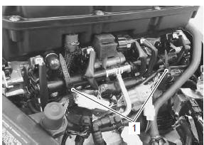
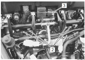
- Disconnect the respective vacuum hoses (2) from vacuum nipples on the throttle body.
- Disconnect the iap sensor coupler (3).
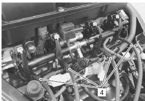
- Connect the respective vacuum tester hoses (4) to the vacuum nipples.
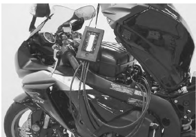
- Set up the sds tool. (Refer to the sds operation manual for further details.)
- Start the engine.
- Click “data monitor”.
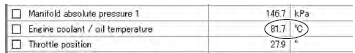
- Warm up the engine (engine coolant temp. More than 80 °c (176 °f)).
- Click “active control”.
- Click “isc air volume control” (5).
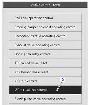
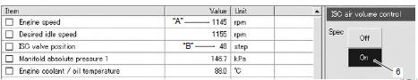
- Click “on” button (6) to fix the isc air volume of four cylinders.
| Note when making this synchronization, be sure that the engine coolant temperature is within 80 – 100 °c (176 – 212 °f). |
|
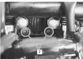
- Check for the synchronization of vacuum from #1 to #4 cylinders.
- Equalize the vacuum of the cylinders by turning each air screw (7) and keep it running at idling speed.
| Note always set the engine rpm at idle rpm. |
- If the adjustment is not yet correct, remove each air screw and clean them with a spray-type carburetor cleaner and blow dry with a compressed air. Also, clean the air screw passageways.
Note
|
- Repeat the procedures from 9) to 16).
- Close the sds tool and turn the ignition switch off.
- Disconnect the vacuum tester and reinstall the removed parts.
- After completing the throttle valve synchronization, clear the dtc and reset the isc learned value using sds tool. Refer to “isc valve preset and opening initialization” in section 1c .
 Isc valve visual inspection
Visually inspect the isc valve if necessary.
Inspect the isc valve for any carbon deposition
defects. Clean or replace the isc valve if necessary.
...
 Isc valve reset
When removing or replacing the throttle body assembly,
reset the isc valve learned value in the following
procedures:
turn the ignition switch on position.
Set up the sds tools. (Refer t ...
Other materials:
Using the testers
Incorrectly connecting the (+) and (.) Probes may
cause the inside of the tester to be burned.
If the voltage and current are not known, make
measurements using the highest range.
When measuring the resistance with the multi-circuit
tester (1), ∞ will be shown as 10.00 ...
Evap canister hose routing diagram (only
for e-33)
Evap system purge control solenoid valve
Surge hose
Purge hose
Fuel shut-off valve
Rear fender
Evap canister
Seat hook
White marking
Yellow marking
Up
Face the
clamp end downward
Face the
clamp end to the left
Pass the
...
Gearshift shaft / gearshift cam plate removal
and installation
Removal
Remove the engine sprocket cover. Refer to “engine sprocket removal and
installation” in section 3a .
Remove the clutch components. Refer to “clutch removal” in section 5c .
Remove the snap ring (1) and washer (2) from the
gearshift shaft.
Special tool
: 09900–06 ...